Saturday, October 2, 2010
Friday, October 1, 2010
Thursday, September 30, 2010
Reed Shaper
Abstract
In the process of double reed making for musical instruments such as oboe, oboe d’amore, English horn and bassoon, the cane is tied onto the metal tube of a so-called staple. Prior to that, the cane is gauged to a standard shape, soaked in water, either “folded completely over upon itself and then clamped and cut to shape on a shaper tip tool” or “clamped and cut to shape on a flat shaper tool and then folded”.
The Reed Shaper deals with the main disadvantages of the flat shaper tool which are the difficulty to exactly position the cane on the shaper and to fold the shaped cane exactly on a line indicated by markings on the flat shaper tool. Failure to do this very precisely will cause a mismatch of the two half reed’s shapes or the way they are tide down on the conically, oval shaped staple.
The Reed Shaper teaches a simple handheld novel flat shaper tool that can be economically manufactured and provides means to press a fold score in a radial as well as lateral rigorously aligned cane and tight fitting precise shape cutting guidance below as well as above the cane.
None of the devices of the state of art provide means to press a fold score in a radial as well as lateral rigorously aligned cane and means to provide tightly fitting precise shape cutting guidance below as well as above the cane in a single, simple, economical, lightweight and compact device.
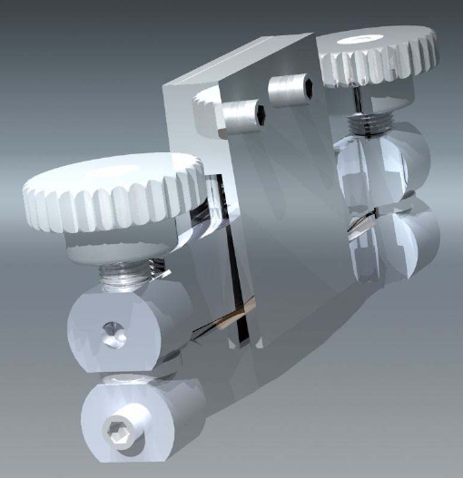 |
The reed shaper, held together as a compact, about 125 x 70 x 25 mm package. |
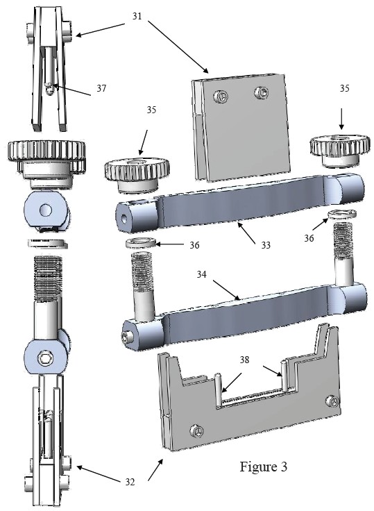
In figure 3 the eight components and subassemblies are separated consisting of:
- radial aligner 31 with guiding pins 37,
- lateral aligner 32 with guiding pins 38,
- upper lid 33,
- lower lid 34,
- two knobs 35,
- two washers 36.
The method and device of the invention will be further described hereunder by going over the steps required to make a radial and lateral aligned folded cane. |
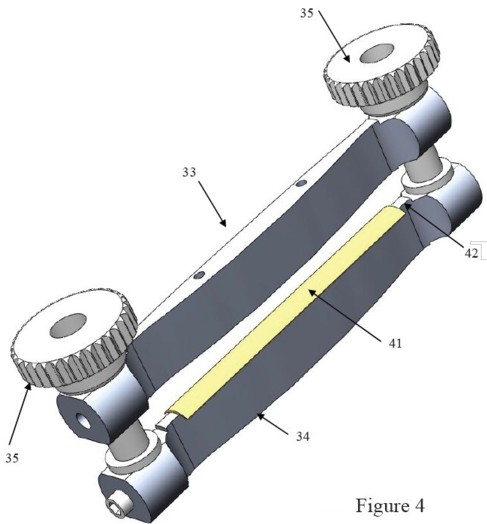
Step 1 loading
Illustrated in figure 4 is a gouged piece of cane 41 loaded on the rounded top 42 of lower lid 34. The rounding of top 42 corresponds to the inner diameter of the gouged cane, which typically has a 4:3 ratio with the bed diameter of the gouging machine (typically 11 mm). To gain access, the knobs 35 and upper lid 33 have to be raised.
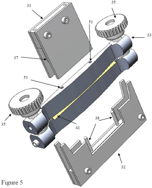
Step 2 loosely tightening
Figure 5. Lower the upper lid 33 so that it rests against the top of the cane 41 and either loosely tighten the knobs 35 or hold the shaper device such that the weight of the upper lid 33 will slightly press cane 41 down by gravity. The lower side of upper lid 33 that rests against the topside of the cane is formed by a cylindrical cutout of bed 124, shown in detail in figure 12, which has a diameter equivalent with the diameter of the gouging machine bed, typically 11mm, used to gouged the cane. This should create a tight fit when the lids are later tightened against the cane. The loose tightening will keep the cane 41 on the rounded top 42 while still allowing the cane 41 to be shifted by the aligners 31 and 32. Both aligners have each a pair of guiding pins 37 or 38 entering into guiding holes 51 provided in both the upper and lower lid.
Step 3 radial alignment
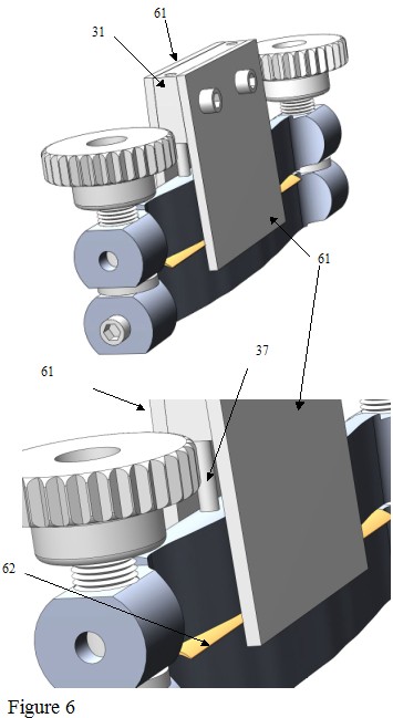
See figure 6. Sliding the radial aligner 31 up and down guided by pins 37 moves the two slightly slanted sideplates 61. This motion varies the proximity of the sideplate’s inner surface area to the side edge 62 of cane 41. The sideplates get closer to the cane’s edge when lowering the radial aligner and farther when raising the aligner. The radial aligner is lowered until contact is made with the cane while further lowering will shift the cane into radially centering. Up to the point when the cane is fully radially aligned, the resistance against further lowering is relatively small. This resistance will drastically go up when the operator starts to deform the cane, at which point no further lowering is required.
Step 4 lateral alignment
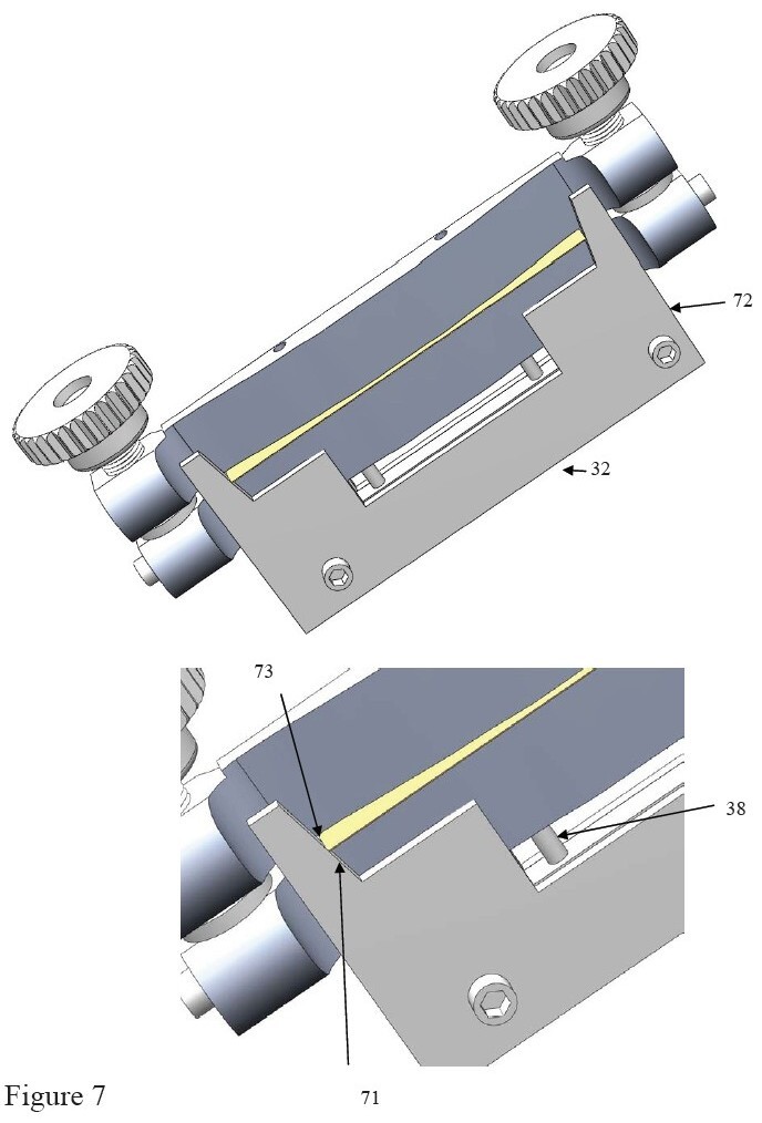
See figure 7. Sliding the lateral aligner 32 up and down guided by pins 38 moves the two slightly angled parts 71 of the two sideplates 72. This motion varies the proximity of the sideplate’s 72 slightly angled parts’ 71 inner surface areas to the end edges 73 of cane 41. The sideplate’s parts 71 get closer to the cane’s edge 73 when raising the lateral aligner and farther when lowering this aligner 32. The lateral aligner is raised until contact is made with the cane while further raising will shift the cane into lateral centering. Up to the point when the cane is fully laterally aligned, the resistance against further lowering is relatively small. This resistance will drastically go up when the operator starts to deform the cane, at which point no further lowering is required.
Step 5 tightening and scoring
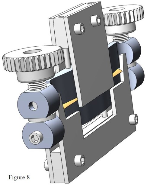
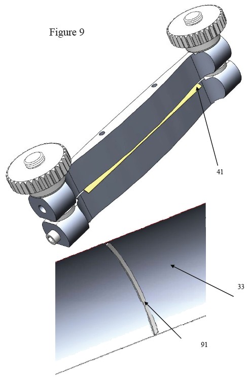
See figures 8 and 9. Figure 8 shows both aligners pressed against cane at all points of contact at which point the knobs 35 can be tightened firmly. The cane 41 will now be secured into that centered aligned position. Figure 9 shows the tightened down shaper with pieces of excess cane sticking out from in between the lids while both aligners are removed. The thread of the knobs can be made fine enough to provide a large compressing force in combination with a large knob diameter to ease operating of the shaper. A scoring blade 91 is present in the bed 124, see figure 12, of the upper lid 33 at the symmetry axis of the lid’s shape that will be pressed into the outside of cane 41 making a score that will facilitate to fold the cane at the desired position.
Step 6 shaping
Figure 10 shows on the left the tightened shaper after shaping during which the excess cane is removed. On the right, an opened shaper from which a scored shaped cane 101 can be removed.
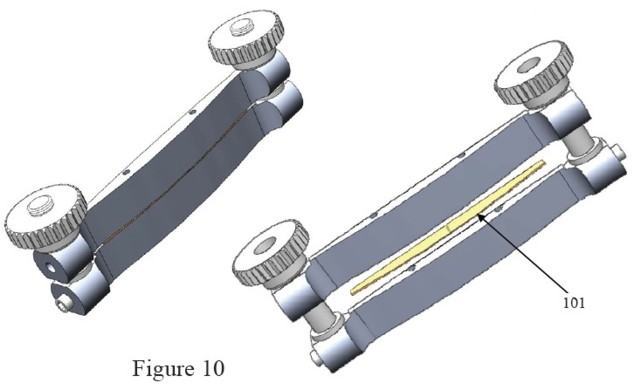
Figure 11 shows in the upper half a scored and shaped cane while showing the end result in the form of a folded shaped cane in the lower half.
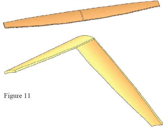
Figure 12b shows the bottom view revealing the, typically 11mm diameter, bed 124 that is pressed against the outside of the cane.
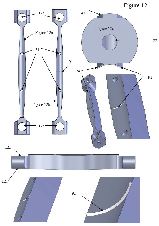
Figure 12b also shows the scoring blade 91 that most conveniently can be machined into the shaper from the rod material. Alternatively, a separate blade could be inserted in a slot in the lid, e.g., gluing it in. The blade should be dimensioned to cut only into a fraction of the cane which is determined by the size of the blade in combination with the thickness of the washers 36. In a tightened down situation, the washers are pressed against the flat sides 121 at the end of the rods. Starting from the harder outside layer of the cane, sufficient softer inside material should remain uncut in order to make an appropriately folded cane. Figure 12c shows drilled out opening 122 at the ends of the rod allowing to enter a bolt in a corresponding threaded hole in the stud that slides through the cylindrical openings 123. The stud is threaded on one end enabling to hold the knobs.
Copyright © 2010 - Reedshaper.com - Patent pending